Features
|
Dimensional Drawing
|
Specifications
|
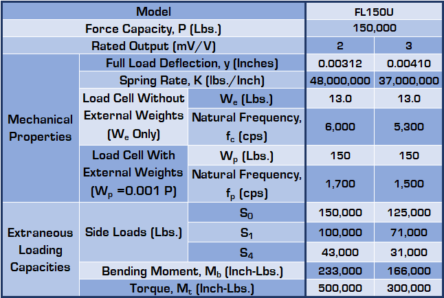
Mechanical Properties
|
Performance Specs
|
Electrical Specifications
Features
|
|

Specifications
Load Capacity |
N/A 150,000 lb |
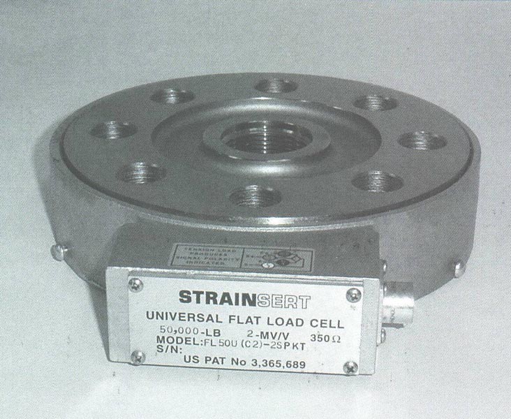
Type of Flat Load Cells |
N/A Universal |
Rated Output |
N/A 2-mV/V (Nominal) 2-mV/V (Std. Output) 3-mV/V (Nominal) 3-mV/V (Std. Output) |
Configuration |
N/A Dual Bridge Single Bridge |
Non-Linearity |
N/A General Purpose ±0.25% F.S. Precision ±0.10% F.S. |
Connector Type |
N/A Connector Permanently Attached Cable |
Hole Type |
N/A Threaded Loading Hole Thru Hole |
A - Diameter |
N/A 4-3/8 in |
B - Diameter |
N/A 7 in |
C - Diameter |
N/A 10-3/4 in |
D - Diameter |
N/A 11-1/8 in |
E - Length |
N/A 12-11/16 in |
F - Height |
N/A 1-1/2 in |
G - Width |
N/A 3-3/4 in |
H - Height |
N/A 3-1/2 in |
K - Outside Diameter |
N/A 1-3/16 in |
k - Inside Diameter |
N/A 13/16 in |
Number of Hold Down Bolt Holes |
N/A 16 |
L - Diameter |
N/A 8-3/4 in |
M - Length |
N/A 9/16 in |
N - Depth of Hole |
N/A 1-1/8 in |
T - Hole |
N/A 2-3/8-12N-2B Thru Hole, 2-13/32" |
Lifting Holes - Threads |
N/A 3/8-16 UNC |
Lifting Holes - BC. Diameter |
N/A 3-1/8 |
Weight |
N/A 59.5 lb |
Performance Specs
Accuracy |
N/A |
Non-Linearity |
N/A General Purpose ±0.25% FS Precision ±0.10% FS |
Hysteresis |
N/A General Purpose ±0.15% FS Precision ±0.10% FS |
Non-Repeatability |
N/A ±0.05% FS |
Environmental |
N/A |
Compensated Range |
N/A 60 to 150 ºF |
Effect on Zero |
N/A ±0.0035% FS/°F |
Effect on Output |
N/A ±0.0030% Load/°F (Nominal) |
Electrical |
N/A |
Excitation Voltage |
N/A 15V AC or DC (Maximum) |
Bridge Resistance |
N/A 350 Ohms (Nominal) |
| Zero Balance1 | N/A ±2% FS (Nominal) |
Insulation Resistance |
N/A 10,000 Megaohms (Minimum) |
Mechanical |
N/A |
Safe Static Overload without Zero Shift |
N/A 200%FS |
Safe Static Overload without Output Shift |
N/A 200%FS |
Safe Static Overload without Structural Failure |
N/A 250%FS |
Electrical Specifications
Receptacle |
N/A PT02H-10-6P |
Mating Plug |
N/A PT06A-10-6S (SR) |
Function |
N/A Pin |
(+) Excitation |
N/A A |
(-) Excitation |
N/A D |
(+) Signal |
N/A B |
(-) Signal |
N/A C |
Cable |
N/A #20(26x34) AWG., rubber insulation, shielded, rubber jacket, 4-Conductor (Standard Cable) |
Function |
N/A Wire Code |
(+) Excitation |
N/A Red |
(-) Excitation |
N/A Black |
(+) Signal |
N/A Green |
(-) Signal |
N/A White |
- 1 Prior to loading, it is necessary to initially/periodically null the zero load output to account for any residual offset.