Features
|
|

Specifications
Load Capacity |
N/A 65,000 lb |
Wire Rope Diameter |
N/A 1.13 Inch |
Material |
N/A Stainless Steel 17-4, H-1025 (Standard) |
A - Width of Center Loading Section |
N/A 1-5/8 in |
B - Width of Clevis Support Section |
N/A 13/16 in |
C - Length of Pin Reduced Section, Instrumented Zone |
N/A 5/8 in |
Dp - Nominal Pin Diameter |
N/A 2.250 in |
E - Active Length of Pin |
N/A 4-1/2 in |
F - Clevis Pin Head Length |
N/A 2 in |
G - Extension of Pin for Keeper Plate Installation |
N/A 5/8 in |
H - Width of Keeper Plate Slot |
N/A 17/64 in |
J - Depth of Keeper Plate Slot |
N/A 3/8 in |
L - Overall Length of Pin |
N/A 7-1/8 in |
U - Nominal Spacer Thickness |
N/A 1/8 in |
Weight |
N/A 7.5 lb |
Safety Factor |
N/A 3.8 |
Keeper Plates |
N/A SPA-65-112-1-A |
Connector Type |
N/A Axial Connector Permanently Attached Axial Cable |
Performance Specs
Overload without Zero Shift |
N/A 150% |
Overload without Failure |
N/A 300% (Minimum) |
Bridge |
N/A Full bridge 350 Ohm (Nominal) |
Excitation |
N/A 12 V AC (Maximum) 12 V DC (Maximum) |
| Output Signal1 | N/A 2-mV/V (Nominal) 2-mV/V (Standardized Output) |
Non-Repeatability |
N/A ±0.15% FS (Nominal) |
Non-Linearity |
N/A ±0.50% FS (Nominal) |
Hysteresis |
N/A ±0.50% FS (Nominal) |
Service Temp Range |
N/A to 150 °F |
Temp Effects (on Zero) |
N/A 0.005% FS / °F (Nominal) |
Temp Effects (on Output) |
N/A 0.008% load / °F (Nominal) |
| Zero Balance2 | N/A ±2% FS (Nominal) |
Electrical Specifications
Receptacle |
N/A PTIH-10-6P |
Mating Plug |
N/A PT06A-10-6S (SR) |
Function |
N/A Pin |
(+) Excitation |
N/A A |
(-) Excitation |
N/A D |
(+) Signal |
N/A B |
(-) Signal |
N/A C |
Cable |
N/A #20(26x34) AWG., rubber insulation, shielded, rubber jacket, 4-Conductor (Standard Cable) |
Function |
N/A Wire Code |
(+) Excitation |
N/A Red |
(-) Excitation |
N/A Black |
(+) Signal |
N/A Green |
(-) Signal |
N/A White |
General Information
|
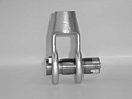
Wire Rope Load Pins are strain gage transducers developed by Strainsert (U.S. Patent No. 3,695,096). They are manufacured utilizing the internal strain gage process perfected by Strainsert since 1960. We offer precision force measurement by simply replacing existing wire rope load pins. |
- 1 Exact output provided with calibration data. (Standardized outputs are optional). In addition, Strainsert factory calibrations are intended to simulate installed conditions, however, it is recommended that an in-place calibration be performed to account for any installation, tolerance, and/or alignment influences affecting sensor measurement.
- 2 Prior to loading, it is necessary to initially/periodically null the zero load output to account for any residual offset.