Dual Bridge Clevis Pins
Load Pin Optional Features


Dual Bridge Clevis Pins provide two independent strain gage circuits. Dual Bridge transducers may use both bridges for simultaneous control and measurement or use a single bridge for measurement with the other bridge reserved as a spare.
Electrical terminations can be radial or axial using either single or dual connectors (dual shown below). Permanently attached cables can also be provided
Electrical terminations can be radial or axial using either single or dual connectors (dual shown below). Permanently attached cables can also be provided
Item # |
Bridge Composition |
Bridge Excitation |
Bridge Resistance |
Bridge Sensitivity |
Temperature, Zero Load |
Temperature, F.S. Load |
Zero Balance |
Non-Repeatability |
Non-Linearity |
Hysteresis |
Safe Overload |
Ultimate Strength |
Minimum Pin Diameter |
Material |
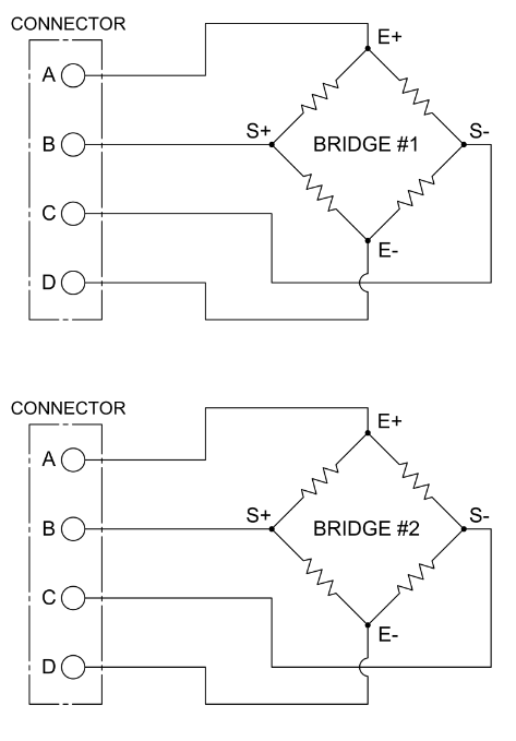
Dual Bridge Wiring Diagram |
Mechanical Properties |
|---|---|---|---|---|---|---|---|---|---|---|---|---|---|---|---|---|
| Dual Bridge | Bridge Composition N/A Full | Bridge Excitation N/A 10 (typical), 12 maximum Vdc | Bridge Resistance N/A 350 (nominal) Ohm | Bridge Sensitivity N/A 0.5 and higher mV/V | Temperature, Zero Load N/A 0.01% (nominal) ±F.S./°F | Temperature, F.S. Load N/A 0.01% (nominal) load/°F | Zero Balance N/A 3.0% (nominal) ±F.S. | Non-Repeatability N/A 0.25% (nominal) ±F.S. | Non-Linearity N/A 1 % (nominal) ±F.S. | Hysteresis N/A 1 % (nominal) ±F.S. | Safe Overload N/A 150% (typical) ±F.S. | Ultimate Strength N/A 300% (typical) ±F.S. | Minimum Pin Diameter N/A 1 (standard), 0.5 (with limitations) inch | Material N/A 17-4 Stainless Steel (typical) |
Dual Bridge Wiring Diagram
N/A dual-bridge-wiring-diagram |
Mechanical Properties N/A |
