Features
|
|

Specifications
| Load Capacity1 | N/A ±120, C/R KIPS180, U/D KIPS |
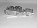
Type of Flat Load Cells |
N/A Fatigue Rated |
Rated Output |
N/A 2-mV/V C/R (Nominal) 2-mV/V C/R (Std. Output) 3-mV/V U/D (Nominal) 3-mV/V U/D (Std. Output) |
Configuration |
N/A Dual Bridge Single Bridge |
Non-Linearity |
N/A General Purpose ±0.25% F.S. Precision ±0.10% F.S. |
Connector Type |
N/A Connector Permanently Attached Cable |
Hole Type |
N/A Threaded Loading Hole Thru Hole |
A - Diameter |
N/A 5 in |
B - Diameter |
N/A 9-1/4 in |
C - Diameter |
N/A 14-1/2 in |
D - Diameter |
N/A 15 in |
E - Length |
N/A 16-1/2 in |
F - Height |
N/A 1-1/2 in |
G - Width |
N/A 3-3/4 in |
H - Height |
N/A 4 in |
K - Outside Diameter |
N/A 1-5/8 in |
k - Inside Diameter |
N/A 1-1/16 in |
Number of Hold Down Bolt Holes |
N/A 16 |
L - Diameter |
N/A 11-3/4 in |
M - Length |
N/A 11/16 in |
N - Depth of Hole |
N/A 1-3/4 in |
T - Hole |
N/A 3-12N-2B Thru Hole, 3-1/32" |
Lifting Holes - Threads |
N/A 3/8-16 UNC |
| Lifting Holes - BC. Diameter2 | N/A 4-1/8 |
Basic Model |
N/A FL300U-2 |
Weight |
N/A 170 lb |
Performance Specs
Fatique Life |
N/A One Billion (109) Cycles |
Bridge Resistance |
N/A 350 Ohms (Nominal) |
Excitation Voltage |
N/A 15V AC or DC (Maximum) |
Compensated Range |
N/A 60 to 150 ºF |
Temperature Effect on Bridge Balance |
N/A ±0.0035% FS/°F |
Temperature Effect on Output Signal |
N/A ±0.0030% Load/°F (Nominal) |
Non-Repeatability |
N/A ±0.05% FS |
Non-Linearity |
N/A ±0.25% FS |
Hysteresis |
N/A ±0.15% FS |
Bridge Balance |
N/A ±2% FS |
Insulation Resistance |
N/A 10,000 Megaohms (Minimum) |
Electrical Specifications
Receptacle |
N/A PT02H-10-6P |
Mating Plug |
N/A PT06A-10-6S (SR) |
Function |
N/A Pin |
(+) Excitation |
N/A A |
(-) Excitation |
N/A D |
(+) Signal |
N/A B |
(-) Signal |
N/A C |
Cable |
N/A #20(26x34) AWG., rubber insulation, shielded, rubber jacket, 4-Conductor (Standard Cable) |
Function |
N/A Wire Code |
(+) Excitation |
N/A Red |
(-) Excitation |
N/A Black |
(+) Signal |
N/A Green |
(-) Signal |
N/A White |
General Information
|
Load Cells are strain gage transducers developed by Strainsert (U.S. Patent No. 3,695,096). They are manufacured utilizing the internal strain gage process perfected by Strainsert since 1960. |
- 1 U/D: Uni-directional load rating, from zero to maximum specified. C/R: Completely reversed load rating, plus and minus specified.
- 2 Bolt Circle Diameter